Difference between revisions of "Element Types"
| (19 intermediate revisions by the same user not shown) | |||
| Line 1: | Line 1: | ||
This section lists the elements that can be used in FEA calculations | This section lists the elements that can be used in FEA and MPM calculations | ||
== FEA Element Types == | == FEA Element Types == | ||
| Line 13: | Line 13: | ||
* <tt>8</tt> or "9 Node Lagrange": 9-node Langrangian rectangular element (quadratic) (9 point Gaussian quadrature) | * <tt>8</tt> or "9 Node Lagrange": 9-node Langrangian rectangular element (quadratic) (9 point Gaussian quadrature) | ||
These FEA element types are illustrated in the following | These FEA element types are illustrated in the following figure. | ||
[[File:FEAElements.jpg|center]] | [[File:FEAElements.jpg|center]] | ||
| Line 24: | Line 24: | ||
* <tt>6</tt> or "6 Node Interface": 6-node [[Imperfect Interfaces|imperfect interface]] elements (quadratic) | * <tt>6</tt> or "6 Node Interface": 6-node [[Imperfect Interfaces|imperfect interface]] elements (quadratic) | ||
These FEA element | These FEA interface element types are illustrated in the following figure. Note that imperfect interface elements are comprised of two separate [[Path Command|paths]] with identical nodal coordinates and thus twice as many actual nodes as appear in the figure. | ||
[[File: | [[File:InterfaceElements.jpg|center]] | ||
== Scripted Input Files == | == Scripted Input Files == | ||
| Line 34: | Line 34: | ||
Element (elem) | Element (elem) | ||
where <tt>(elem)</tt> is a number or name from the [[#FEA Element Types|above | where <tt>(elem)</tt> is a number or name from the [[#FEA Element Types|above lists]] (by name or number). Once an element is selected, it remains the element used for all subsequent [[Area Command|Area commands]]. If no <tt>Element</tt> command has been used, FEA calculations will default to "8 Node Quadrilateral" elements. Solid (or quadrilateral) [[Area Command|areas]] can only use [[#Solid Elements|solid elements]] while interface [[Area Command|areas]] can use only [[#Interface Elements|interface elements]]. | ||
The command to flip triangles is | When using triangular elements (type 1 and 4), quadrilateral areas meshed using the [[Area Command]] first meshes the area into quadrilaterals and then creates triangular elements by dividing each quadrilaterals along its diagonal. To determine which diagonal in used, you can use the <tt>FlipTriangles</tt> command: into triangular elements. The command to flip triangles is | ||
FlipTriangles <(option)> | FlipTriangles <(option)> | ||
where <tt>(option)</tt> is <tt>yes</tt> or <tt>no</tt> to flip or not flip the triangles. This argument is optional. If it is omitted, the command will toggle the previous setting for triangle flipping. The initial value is always <tt>no</tt>. | where <tt>(option)</tt> is <tt>yes</tt> or <tt>no</tt> to flip or not flip the triangles. This argument is optional. If it is omitted, the command will toggle the previous setting for triangle flipping. The initial value is always <tt>no</tt>. Any new setting by a <tt>FlipTriangles</tt> command remains in effect until it is changed by another <tt>FlipTriangles</tt> command. | ||
== XML Input Files == | |||
In <tt>XML</tt> input files, the first [[Area Command#XML Area Block|<tt><Area></tt> block]] must define an element <tt>type</tt> in an attribute and refer to it by number from the [[#FEA Element Types|above list]]. Subsequent <tt><Area></tt> blocks can omit the <tt>type</tt> attribute unless the element type is changed to have an analysis with mixed elements. Solid (or quadrilateral) [[Area Command#XML Area Block|areas]] can only use [[#Solid Elements|solid elements]] while interface [[Area Command#XML Area Block|areas]] can use only [[#Interface Elements|interface elements]]. For triangular elements, the diagonals are flipped using a <tt>flip</tt> attribute on the [[Area Command#XML Area Block|<tt><Area></tt>]] command instead of using a separate [[#Scripted Input Files|<tt>FlipTriangles</tt> command]]. | |||
== MPM Element Types == | |||
In theory, MPM could use any element type in the background. In practice, all MPM codes use linear elements and unpublished attempts to try other element types have not been successful. Furthemore, many MPM features required a regular orthogonal grid, although there is no particular need for grid spacings to be the same in all directions. As a result, MPM in 2D and 3D uses the following two types of elements | |||
* <tt>2</tt> or "4 Node Quadrilateral": 4-node rectangular (usually) elements (linear) for 2D MPM | |||
* <tt>7</tt> or "8 Node Brick": 8-node rectangular box (usually) elements (linear) for 3M MPM | |||
These MPM element types, in there usual shape, are illustrated in the following figure. | |||
[[File:MPMElements.jpg|center]] | |||
== Notes == | == Notes == | ||
# When | # When different element types are using in a single analysis (including mixing of [[#Solid Elements|solid elements]] and [[#Interface Elements|interface elements]]), they must all be compatible elements. In other words, you can mix linear elements (types 1, 2, and 5) with each other or quadratic elements (types 3, 4, 6, and 8) with each other, but cannot mix linear elements with quadratic elements in the same mesh. | ||
Latest revision as of 10:48, 15 November 2013
This section lists the elements that can be used in FEA and MPM calculations
FEA Element Types
Solid Elements
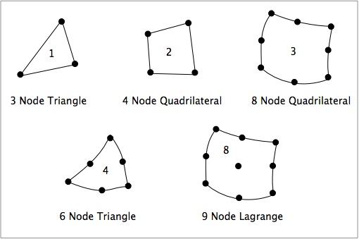
The following solid elements are currently available in NairnFEA:
- 1 or "3 Node Triangle": 3-node constant-strain triangular elements (linear)
- 2 or "4 Node Quadrilateral": 4-node isoparametric rectangular elements (linear)
- 3 or "8 Node Quadrilateral": 8-node isoparametric rectangular elements (quadratic)
- 4 or "6 Node Triangle": 6-node isoparametric triangular elements (quadratic)
- 8 or "9 Node Lagrange": 9-node Langrangian rectangular element (quadratic) (9 point Gaussian quadrature)
These FEA element types are illustrated in the following figure.
Interface Elements
The following interface elements are used to model imperfect interface:
- 5 or "4 Node Interface": 4-node imperfect interface elements (linear)
- 6 or "6 Node Interface": 6-node imperfect interface elements (quadratic)
These FEA interface element types are illustrated in the following figure. Note that imperfect interface elements are comprised of two separate paths with identical nodal coordinates and thus twice as many actual nodes as appear in the figure.
Scripted Input Files
In scripted input files, the element type is set using the Element command:
Element (elem)
where (elem) is a number or name from the above lists (by name or number). Once an element is selected, it remains the element used for all subsequent Area commands. If no Element command has been used, FEA calculations will default to "8 Node Quadrilateral" elements. Solid (or quadrilateral) areas can only use solid elements while interface areas can use only interface elements.
When using triangular elements (type 1 and 4), quadrilateral areas meshed using the Area Command first meshes the area into quadrilaterals and then creates triangular elements by dividing each quadrilaterals along its diagonal. To determine which diagonal in used, you can use the FlipTriangles command: into triangular elements. The command to flip triangles is
FlipTriangles <(option)>
where (option) is yes or no to flip or not flip the triangles. This argument is optional. If it is omitted, the command will toggle the previous setting for triangle flipping. The initial value is always no. Any new setting by a FlipTriangles command remains in effect until it is changed by another FlipTriangles command.
XML Input Files
In XML input files, the first <Area> block must define an element type in an attribute and refer to it by number from the above list. Subsequent <Area> blocks can omit the type attribute unless the element type is changed to have an analysis with mixed elements. Solid (or quadrilateral) areas can only use solid elements while interface areas can use only interface elements. For triangular elements, the diagonals are flipped using a flip attribute on the <Area> command instead of using a separate FlipTriangles command.
MPM Element Types
In theory, MPM could use any element type in the background. In practice, all MPM codes use linear elements and unpublished attempts to try other element types have not been successful. Furthemore, many MPM features required a regular orthogonal grid, although there is no particular need for grid spacings to be the same in all directions. As a result, MPM in 2D and 3D uses the following two types of elements
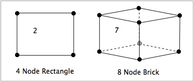
- 2 or "4 Node Quadrilateral": 4-node rectangular (usually) elements (linear) for 2D MPM
- 7 or "8 Node Brick": 8-node rectangular box (usually) elements (linear) for 3M MPM
These MPM element types, in there usual shape, are illustrated in the following figure.
Notes
- When different element types are using in a single analysis (including mixing of solid elements and interface elements), they must all be compatible elements. In other words, you can mix linear elements (types 1, 2, and 5) with each other or quadratic elements (types 3, 4, 6, and 8) with each other, but cannot mix linear elements with quadratic elements in the same mesh.


