Difference between revisions of "Explicit FEA Cracks"
| Line 16: | Line 16: | ||
== Crack Tip Command == | == Crack Tip Command == | ||
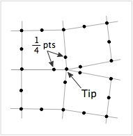
The <tt>CrackTip</tt> coverts all elements at the crack tip to be quarter point elements. Quarter point elements are [[FEA Elements|6 or 8-node quadratic elements]] where the midside nodes near the crack tip are 1/4 of the way from the tip node to the next edge node rather than half way as in conventional quadratic elements (see figure on the right). Quarter point elements at the crack tip are created by creating a mesh with | [[File:qtrpt.jpg|right]] | ||
The <tt>CrackTip</tt> coverts all elements at the crack tip to be quarter point elements. Quarter point elements are [[FEA Elements|6 or 8-node quadratic elements]] where the midside nodes near the crack tip are 1/4 of the way from the tip node to the next edge node rather than half way as in conventional quadratic elements (see figure on the right). Quarter point elements at the crack tip are created by first creating a mesh with [[FEA Elements|8-node quadrilaterals or 6-node triangles]] and then adding the command: | |||
CrackTip (keyid) | |||
or | |||
CrackTip | CrackTip (x),(y) | ||
where | |||
* (keyid) specifies a previously defined [[Keypoint Command|keypoint]] located at the crack tip. | |||
* Alternatively, the crack tip can be specified by the (<tt>(x),(y)</tt>) coordinates (in mm). The node closest to that point will be the crack tip node. | |||
</ | In theory, quarter point elements represent the singular stress field of a crack tip better than conventional elements. They were first proposed by Barsoum (1974).<ref name='qtr'>R. S. Barsoum, "Application of Quadratic Isoparametric Finite Elements in Linear Fracture Mechanics," <i>Int. J. Fracture</i>, <b>10</b>, 603-605 (1974).</ref> Quarter point element are available in [[NairnFEA]] for research use, but they have drawbacks, and therefore are not recommended. Recent experience with crack-closure calculations shows that they converge more slowly to the correct result than conventional mid-side nodes and prior literature has errors in the crack-closure equations.<ref name='CC'/> Furthermore, visualization of strain from FEA results is done by differentiation of the displacement field. Since quarter-point elements have singular strains at the crack tip, the strain in those element will be undefined. These elements can still plot stresses. | ||
== References == | == References == | ||
<references/> | <references/> | ||
Revision as of 09:17, 12 September 2013
FEA calculations can model explicit cracks.
Explicit Cracks
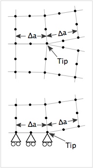
Cracks in FEA calculations are set up by configuring the mesh to include a crack. A crack can be internal to the mesh or, for symmetric loading, can be on an edge of the mesh and defined with the help of boundary conditions. These two crack geometries are illustrated on the right. In the first form, the two element edges to the right of the crack tip are initially aligned on the same coordinates. When the crack is loaded in tension, the edges separate and the point where they are joind is the crack tip. The static FEA run in NairnFEA does not include contact and therefore only opened crack can be modeled.
The second form of crack is for symmetric loading. The crack plane is on the bottom of the object and the displacement boundary conditions determine the location of the crack tip
Crack Closure Calculations
In crack closure calculations, nodal forces and displacements are used to find mode I and mode II energy release rate for crack growth. The calculations are done after the analysis is done and NairnFEAMPM is configured to do the calculations. A recent paper on crack closure calculations for a variety of elements and allowing for crack surface tractions is in Nairn (2012).[1]. This reference was the bases of the NairnFEAMPM calculations. That pointed pointed out the for the best results, the crack plane edges in front of and behind the crack tip must initially be collinear and of be of equal length (Δa).
Crack closure calculations can be done for any element type allowed in NairnFEA. In addition, one special crack tip element available and it is selected using the CrackTip command.
Crack Tip Command
The CrackTip coverts all elements at the crack tip to be quarter point elements. Quarter point elements are 6 or 8-node quadratic elements where the midside nodes near the crack tip are 1/4 of the way from the tip node to the next edge node rather than half way as in conventional quadratic elements (see figure on the right). Quarter point elements at the crack tip are created by first creating a mesh with 8-node quadrilaterals or 6-node triangles and then adding the command:
CrackTip (keyid)

   or

CrackTip (x),(y)
where
- (keyid) specifies a previously defined keypoint located at the crack tip.
- Alternatively, the crack tip can be specified by the ((x),(y)) coordinates (in mm). The node closest to that point will be the crack tip node.
In theory, quarter point elements represent the singular stress field of a crack tip better than conventional elements. They were first proposed by Barsoum (1974).[2] Quarter point element are available in NairnFEA for research use, but they have drawbacks, and therefore are not recommended. Recent experience with crack-closure calculations shows that they converge more slowly to the correct result than conventional mid-side nodes and prior literature has errors in the crack-closure equations.[1] Furthermore, visualization of strain from FEA results is done by differentiation of the displacement field. Since quarter-point elements have singular strains at the crack tip, the strain in those element will be undefined. These elements can still plot stresses.
References
- ↑ 1.0 1.1 J.A. Nairn, "Generalized Crack Closure Analysis for Elements with Arbitrarily-Placed Side Nodes and Consistent Nodal Forces," Int. J. Fracture, 171, 11-22 (2011). (PDF version)
- ↑ R. S. Barsoum, "Application of Quadratic Isoparametric Finite Elements in Linear Fracture Mechanics," Int. J. Fracture, 10, 603-605 (1974).

