Difference between revisions of "Surface Normals"
| Line 55: | Line 55: | ||
=== Rigid Material Bias Option === | === Rigid Material Bias Option === | ||
When an MPM simulation has contact with [[Rigid Material#Rigid Contact | When an MPM simulation has contact with [[Rigid Material#Rigid Contact Material|rigid contact materials]], the normals from the rigid material may be more reliable (especially if those particles are stationary). The [[Multimaterial MPM#Multimaterial Mode Input Commands|<tt>(rigidBias)</tt> parameter]] can be used to say that the normal is given by the volume gradient of the rigid material unless the volume gradient calculated by current [[Multimaterial MPM#Multimaterial Mode Input Commands|<tt>(normals)</tt> setting]] is this factor larger. Values around 100 will almost always use the rigid material. If the value is too large, an extremely small and inaccurate normal from the rigid material might lead to errors. | ||
The rigid bias option is only active when the [[Multimaterial MPM#Multimaterial Mode Input Commands|<tt>(normals)</tt> setting]] is <tt>maxgrad</tt> or <tt | The rigid bias option is only active when the [[Multimaterial MPM#Multimaterial Mode Input Commands|<tt>(normals)</tt> setting]] is <tt>maxgrad</tt> or <tt>avggrad</tt>. Is default value is 1.0 or no bias for the rigid material's volume gradient. | ||
=== Volume Screening === | === Volume Screening === | ||
Revision as of 13:30, 8 October 2013
Both multimaterial mode MPM and explicit cracks need to calculate surface normals. These normals are a crucial step in accurate contact physics calculations.
Introduction
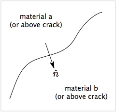
The figure shows a surface between two materials (a and b) or between two sides of a crack (above and below). The arrow shows a vector normal to the surface oriented from side a to side b. Finding this normal accurately is a key component of implementing both multimaterial mode contact and crack contact. First, normals are needed to find the component of the velocity in the approaching direction and the separation in the opening direction, both of which are used to detect contact. Second, the normals are needed to implement contact mechanics such as to model frictional contact or imperfect interfaces.
Practical experience using multimaterial mode MPM simulations has revealed that accuracy of results is very sensitive to the method used to find the normals. In fact, when a multimaterial mode simulation has numerical issues, the causes of those issues is almost always connected to problems in finding surface normals. See below for the various options in multimaterial mode MPM to finding normals. Numerous options are needed because no on option works for all problems.
Simulations that use explicit cracks, have far fewer issues with normals. The normals are still crucial, but because the crack geometry is tracked, the crack normals are more easily calculated. See below for some details on crack surface normals.
Multimaterial Normal Vector Options
NairnMPM has implemented several methods for finding normals in multimaterial mode contact. No one method works for all problems, which is why multiple options are needed. This section describes the available options.
Each Material's Gradient
When multimaterial mode MPM was initially developed, contact was handled separately for each material's velocity field and the normal vector was found from that material's mass gradient.[1] The alorithm is straightforward and is extended to more than two materials in contact simply for iterating for each material. Experience shows it suffers in accuracy compared to methods desribed below. For one thing, the normals for the two materials will generally not be in equal and opposite directions. When that occurs, the contact algorithm does not conserve momentum.
This method is selected by setting (normals) to owngrad (or numerically to 3). This option is available in NairnMPM for comparison to improved methods and not recommended for general use.
Average Gradient
This method (and other improvements below) are described in more detail in Nairn (2013).[2]. The first obvious improvement to conserve momentum is to find the average volume gradient between the two materials and use that vector to define the normal for both sides of the surface. If the multimaterial mode has more than two materials, the average is found between one material and the remaining materials lumped into a virtual material. Note that whenever averaging or comparing gradients, it is important to use volume gradients instead of mass gradients. This minor change is needed to correctly model contact between two materials with different densities.
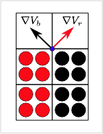
An average gradient calculation can also resolve some complications at edge nodes. The figure on the right shows two materials in contact at the edge of an object. The volume gradients for the red and black materials on the multimaterial node marked in blue are shown by the vectors. Both of these normals are inaccurate for the contacting surfaces, but averaging the normals (with correct signs), gives a normal vector in the horizontal direction that exactly matches the contact surface normal. An average gradient resolves this one edge node issue, but will not correct them all; see the volume screen method for an alternate way to deal with common problems at edge nodes.
This method is selected by setting (normals) to avggrad (or numerically to 2).
Maximum Gradient
This method looks at the volume gradient's for the two materials and choses the vector that has the largest magnitude (and then normalizes to get a unit vector). The logic is that volume gradient is zero within an object and only non-zero around the edge. Thus the material that is closer the edge might have more accurate information about the normal and it will have the larger volume gradient. Perhaps this material's normal should be used in preference to the other material's normal. If the multimaterial mode has more than two materials, the maximum gradient is found by comparing the one material to the remaining materials lumped into a virtual material.
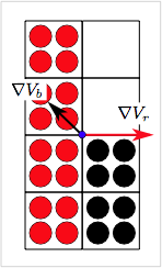
A maximum gradient calculation can also resolve some edge node issues. The figure on the left shows two materials in contact near an edge notch in an object. The volume gradients for the red and black materials on the multimaterial node marked in blue are shown by the vectors. Now the gradient from the red material is correct for the surface normal while the gradient for the black material is not. An average would be better, but still inaccurate. For this situation, the material with the maximum gradient will be the red material (because it has more particles). Therefore this method will get the correct normal. A maximum gradient resolves this one edge node issue, but will not correct them all; see the volume screen method for an alternate way to deal with common problems at edge nodes.
This method is selected by setting (normals) to maxgrad (or numerically to 0).
Maximum Volume
This option looks at the total volume for the two materials and choses the vector using the volume gradient of the material with the larger volume (and then normalizes to get a unit vector). The logic is that multimaterial nodes may have very different volumes between the two materials and one may have very small volume. Because a small volume material may have very inaccurate volume gradient, it is preferable to use the one with more volume. If the multimaterial mode has more than two materials, the maximum volume is found by comparing the one material to the volume of all other materials lumped into a virtual material.
Experience shows this method is less helpful than the average or maximum gradient methods and therefore not recommended. It does, however, also resolve the notch issue for the situation listed under maximum gradient method. By this method the red material has the maximum volume and also has the correct normal vector. See the volume screen method for an alternate way to deal with common problems at edge nodes.
This method is selected by setting (normals) to maxvol (or numerically to 1).
Custom Specified Normal
The ultimate accuracy of normals is sometimes found by specifying the normal in the input file.[2] This option is currently only available in NairnMPM by editing the source code and overriding the normal calculation with a problem-specific normal. This approach only works if the normal can be determined prior to the analysis and if that normal remains the same throughout the analysis. It can be implemented in code and controlled from input files by using developer flags.
Rigid Material Bias Option
When an MPM simulation has contact with rigid contact materials, the normals from the rigid material may be more reliable (especially if those particles are stationary). The (rigidBias) parameter can be used to say that the normal is given by the volume gradient of the rigid material unless the volume gradient calculated by current (normals) setting is this factor larger. Values around 100 will almost always use the rigid material. If the value is too large, an extremely small and inaccurate normal from the rigid material might lead to errors.
The rigid bias option is only active when the (normals) setting is maxgrad or avggrad. Is default value is 1.0 or no bias for the rigid material's volume gradient.
Volume Screening
A common theme in multimaterial contact is that the most severe problems usually occur at nodes near free edges. Furthermore, these problems arise because of inaccuracy in finding the surface normal. The numerical challenge is that volume gradients for multimaterial nodes near free surfaces will be a convolution of free surface normals and contact surface normals; it is not possible to separate them to find just the contact surface normal. Because the contact physics equations need just the contact surface normal, performing contact calculations with a convoluted normal can give poor results.
The examples above illustrate some problems and edge nodes and shows how two specific configurations can be corrected by the average gradient or maximum gradient methods. Unfortunately these two examples are corrected by different methods. In general, no one method can correct all edge nodes issues. Another way to avoid edge nodes problems is simply to ignore contact at edge nodes by screening out those nodes. In other words, multimaterial contact simulations are often improved by ignoring edge nodes rather then including them with inaccurate contact physics. A volume screening option, which described in the help on detecting contact, provide a effective tool for screening out edge nodes.
Explicit Crack Normal Vector
Found from crack path and often more accurate the multimaterial mode such as for interfaces.
References
- ↑ S. G. Bardenhagen, J. E. Guilkey, K. M. Roessig, J. U. Brackbill, W. M. Witzel, and J. C. Foster, "An Improved Contact Algorithm for the Material Point Method and Application to Stress Propagation in Granular Material," Computer Modeling in Engineering & Sciences, 2, 509-522 (2001).
- ↑ 2.0 2.1 J.A. Nairn, "Modeling Imperfect Interfaces in the Material Point Method using Multimaterial Methods," Computer Modeling in Eng. & Sci., 92, 271-299 (2013).


