Detecting Contact
Both multimaterial mode MPM and explicit cracks need to detect when two surfaces are in contact. This page describes the contact detection options.
Basic Contact Detection
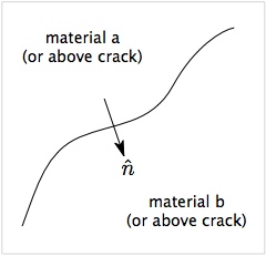
The figure shows a surface between two materials (a and b) or between two sides of a crack (above and below). The arrow shows a vector normal to the surface oriented from side a to side b. For both multimaterial contact and crack contact, the first step is to decide if the two velocity fields at the node are actually in contact. NairnMPM uses two (or more) criteria to detect contact.
- Approach velocity
- The first step is to decide if the two surface are approaching each other in the normal direction. This criterion reduces to [math]\displaystyle{ \Delta\vec v \cdot \hat n \lt 0 \qquad {\rm where} \qquad \Delta\vec v = \vec v_a - \vec v_b }[/math] When this criterion is not satisfied, the surfaces are separating and assumed to not be in contact. In early multimaterial MPM,[1] this criterion alone was assumed sufficient to be in contact. It is easy to visualize, however, that this assumption detects contact when surfaces are approaching each other but are still separated. For improved contact, a second criterion based on displacements is added.
- Displacement check
- If the approach velocity criterion is satisfied, NairnMPM next looks at displacements or positions of the two velocity fields. Basically, this criterion calculates the location of the two surfaces. If they overlap in the normal direction the surfaces are in contact. If they are separated, the surfaces are not in contact. Two ways to find contact surfaces by their surface location are to extrapolate particle displacements or particle positions. These methods are described in the section on the ContactPosition command.
Both multimaterial mode contact and crack contact use the above two criterion, but they have some other options. For example, the displacement check is optional in multimaterial mode but is always done for crack contact. In addition, multimaterial mode has an optional screening criterion based on nodal volume that can help screen out nodes that are likely to cause numerical inaccuracies. See below for details.
Notes
- An accurate normal vector is crucial to contact detection and contact physics.
- Since the displacement check seems to track contact best, why not skip the approach velocity criterion? The answer is that the algorithms used to adjust nodal momementum for some contact physics (e.g., friction) do not make physical sense unless that criterion is satisfied.
Multimaterial Mode Contact Detection
Multimaterial mode uses the above contact methods and has two additional options:
- The displacement check is optional. It can be turned off using the (dispCheck) parameter in the multimaterial mode input commands. The default is to be enabled and the recommendation is to keep it enabled.
- The (Vmin) parameter sets a critical relative volume that will ignore contact for all nodes with total volume below the specified value. It is described in the next section.
Volume Screening for Contact Detection
In volume screening, you set the (Vmin) parameter to a critical volume relative to the total volume of the cells in the background grid. If the volume is below this value, the materials are assumed to not be in contact. If the volume is above this value, the contact detection proceeds with checks on velocity and displacement. One use of this screening is to set it close to 1.0 and then detect contact as a consequence of compression, as reflected by a volume larger than 1.0.[2] The net result is a simple tool for contact detection. Experience in NairnMPM, however, suggest this approach may not be ideal because the simulation results are often too sensitive to the (Vmin) value.
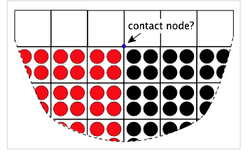
An alternate use of volume screening is to screen out nodes that can potentially cause artifacts in the calculations. These problem nodes are invariably contact nodes that appear near the edge of the modeled object. The figure on the left shows two materials in contact near an edge. The blue node will be a multimaterial node. To detect contact and implement contact physics, the contact algorithm needs to calculate the normal to the contact surface. But for edge nodes these calculations are difficult because the free surface will affect the normal calculation. As a result, the calculation may be inaccurate and the entire simulation can suffer.
This issue can often be fixed by ignoring problem edge nodes. In other words, it can be better to ignore contact on edge nodes then to include them with inaccurate surface normals. Because edge nodes are near empty cells, their total volume from particles will always be less than 1.0. The node in the figure will have total relative volume close to 0.5. Thus to screen out edge nodes, you can set (Vmin) parameter to a value below 1.0, often around 0.5. The goal is to screen out edge nodes but to not screen out any nodes within the object. The actual value is problem dependent. When edge nodes appear to be causing problems in contact calculations, start increasing (Vmin) parameter between 0.0 and 1.0 and hopefully the simulations will improve before getting too close to 1.0.
Explicit Crack Contact Detection
Contact detection for cracks always uses both the approach velocity and the displacement check to decide if the crack surfaces are in contact. The displacement check is more reliable on cracks than between materials because cracks have a better option for finding the crack surface normal.
The only option you can change for crack contact detection is the method to calculate crack surface positions. The details are described in the following section on the ContactPosition command.
ContactPosition Command
When using the displacement check to detect contact, the code extrapolates particle positions within each velocity. The opening displacement normal to the surfaces is found from
[math]\displaystyle{ \delta_n = (\vec x_b-\vec x_a)\cdot\hat n }[/math]
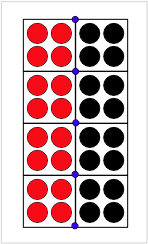
where xa and xb are the extrapolated positions for material above and below the surface and n is the surface normal. But, inherent imprecision of surfaces in MPM (or any particle method) causes a problem. Consider the two surfaces in the figure on the right. When calculations start, their nodal positions extrapolated to common nodes (the blue nodes) will show a positive separation. Calculations with MPM shape functions show that the calculated separation based on positions of two surfaces precisely in contact is
[math]\displaystyle{ \delta_n \approx 0.8\Delta x }[/math]
where Δx is the cell dimension along the contacting axis.[3] In other words, a contact criterion of δn<0 for contact would not detect contact correctly.
Three approaches can resolve this issue:
- Extrapolate particle displacements instead of particle positions to the velocity fields. Now the separation for two surfaces in contact when calculations start is zero and a subsequent finding of δn<0 will indicate contact.
- Define a contact-position offset, such as δcon= 0.8δx and detect contact when δn<δcon.
- Undertake of more precise analysis of relation between extrapolated position of a material and actual distance to a node. First, we write the separation as:
[math]\displaystyle{ \delta_n = d(d_{b,ext})-d(d_{a,ext}) \quad {\rm where} \quad d(d_{m,ext}) = (\vec x_m-\vec x_i)\cdot\hat n }[/math]
where [math]\displaystyle{ d(d_{m,ext}) }[/math] is a function that finds actual distance to a nearby node as a function of the apparent or extrapolated distance. Calculations with MPM shape functions have led to the following function to convert extrapolation distance to actual distance:
[math]\displaystyle{ {d(d_{ext})\over\Delta x} = \left\{\begin{array}{ll} 1-2\left({-d_{ext}\over 1.25}\right)^{0.58} & d_{ext}\lt 0 \\ 2\left({d_{ext}\over 1.25}\right)^{0.58}-1 & d_{ext}\gt 0 \end{array}\right. }[/math]
Contact occurs when [math]\displaystyle{ \delta_n\le0 }[/math]
All three options are available in NairnMPM multimaterial calculations by using (or not using) the ContactPosition command. The first (or displacements) method requires all contact situations to exist in the initial state. This situation is common in crack or interface modeling. The second or third method must be used when these requirements are not met, which is true for any problem where surfaces start out apart and then move into contact during the simulation.
For cracks, the most common approach is to use displacements instead of position with an offset, but cracks that model dynamic interfacial contact might need to switch to a position method instead. One example of this use in cracks is found in a paper on using cracks to model glue bond lines in oriented strand board.[4]
For imperfect interface modeling with cracks or in multimaterial mode, you must use the displacements method whenever the interface law has non-zero tangential traction. The reason is that it is not possible to determine tangential displacement dicontinuity from extrapolated positions. When you must use displacements, the imperfect interfaces must all be in contact in the initial state. This requirement is normally not an issue because interface modeling usually involves interfaces that can be modeled as starting in contact. One issue is if you want to model both dynamic contact that needs position extrapolation along with interfaces that need displacement extrapolation. This type of simulation currently cannot be done, but an alternative is to model the interfaces using a crack with a traction law (although traction laws work with position extrapolations, they are not as accurate as when using extrapolated displacements).
Selecting ContactPosition Options
By default, NairnMPM extrapolates particle displacements to velocity fields and uses relative displacements of the two surfaces to detect contact. To switch to extrapolating particle positions instead and pick a method for converting positions into surface separation, scripted files can add the command:
ContactPosition (cutoff)
and XML files, the command to add is
<ContactPosition>(cutoff)</ContactPosition>
which can be in either the multimaterial block or the explicit cracks block of the <MPMHeader>. In both commands, the value entered for (cutoff) determines the method used:
- (cutoff)> 0: A positive value means to subtract (cutoff) from apparent separation to find actual separation (see method 2 in previous section). When using this method (cutoff) is usually 0.8. If it is decreased, surfaces will visually come into contact before the particles reach each other. If it is larger than 0.8, objects will visually interpenetrate each other before contact is activated.
- (cutoff)< 0: A negative values means to use a function to determine actual separation. The function that is used is given in method 3 in the previous section. The absolute value of the entered parameter is used as the exponent in that power-law expression. It should usually be -0.58 (i.e., exponent wiill be 0.58).
Note that setting (cutoff)=0 is not the same as omitting the command. It will use method 2 in previous section with zero subtraction and result in detecting contact before particles actually reach contact. It should never be done.
Notes
- A single ContactPosition command changes the method used to find surface contact for both multimaterial MPM and explicit cracks (no matter which block specifies it in XML files). It is not possible to combine different position methods in a single simulation. If more than one ContactPosition command is used in the same input commands, the last one will deterimine the cutoff position
- The ContactPosition command should always be present when all or some contacting surfaces are initially separated. Note that the command is essential for handling initially-separated surfaces that later come into contact, and it causes no problems for surfaces that start out in contact. They are still modeled correctly.
- Although the ContactPosition method can handle all contact situations, it is usually more accurate to omit this command when all surfaces are initially in contact. Some exceptions are when the problem has large relative displacements such as sliding of a block or rolling of a disk along a surface; these actually correspond to parts of the surfaces that were separated coming into contact as the simulation evolves.
- For irregular meshes, the absolute cutoff position will depend on the orientation of the crack. The code automatically corrects for this effect using a single input cutoff value by a method described in Nairn (2013).[5]
References
- ↑ S. G. Bardenhagen, J. E. Guilkey, K. M. Roessig, J. U. Brackbill, W. M. Witzel, and J. C. Foster, "An Improved Contact Algorithm for the Material Point Method and Application to Stress Propagation in Granular Material," Computer Modeling in Engineering & Sciences, 2, 509-522 (2001).
- ↑ Jim Guilkey, personal communication, 2012
- ↑ V. Lemiale, A. Hurmane, and J. A. Nairn, "Material Point Method Simulation of Equal Channel Angular Pressing Involving Large Plastic Strain and Contact Through Sharp Corners," Computer Modeling in Eng. & Sci., 70(1), 41-66, (2010).
- ↑ J. A. Nairn and E. Le, "Numerical Modeling and Experiments on the Role of Strand-to-Strand Interface Quality on the Properties of Oriented Strand Board," Proc of 9th Int. Conf. on Wood Adhesives, Lake Tahoe, Neveda, USA, Sept. 28-30, 2009. (See PDF)
- ↑ J.A. Nairn, "Modeling Imperfect Interfaces in the Material Point Method using Multimaterial Methods," Computer Modeling in Eng. & Sci., 92, 271-299 (2013).


