Detecting Contact
Both multimaterial mode MPM and explicit cracks need to detect when two surfaces are in contact. This page describes the contact detection options.
Basic Contact Detection
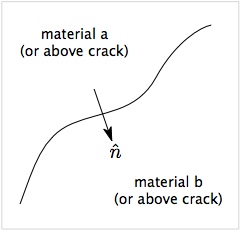
The figure shows a surface between two materials (a and b) or between two sides of a crack (above and below). The arrow shows a vector normal to the surface oriented from side a to side b. For both multimaterial contact and crack contact, the first step is to decide if the two velocity fields at the node are actually in contact. NairnMPM uses two (or more) criteria to detect contact.
- Approach velocity
- The first step is to decide the two surface are approaching each other in the normal direction. This criterion reduces to [math]\displaystyle{ \Delta\vec v \cdot \hat n \lt 0 \qquad {\rm where} \qquad \Delta\vec v = \vec v_a - \vec v_b }[/math] When this criterion is not satisfied, the surfaces are separating and assumed to not be in contact. In early multimaterial MPM,[1] when this criterion is satisfied, the surfaces were assume to be in contact. It is easy to visualize, however, that this approach detects contact when surfaces are just are approaching each other but still separated. For improved contact, a second criterion based on displacements is added.
- Displacement check
- If the approach velocity criterion is satisfied, NairnMPM next looks at displacements or positions of the two velocity fields. Basically, this criterion calculates the location of the two surfaces. If the overlap in the normal direction the surfaces are in contact. If they are separated, the surfaces are not in contact. Two ways to find contact surfaces by their surface location are to extrapolate particle displacements or particle positions. These methods are described in the section on the ContactPosition command.
Both multimaterial mode contact and crack contact use the above two criterion, but they have some other options. For example, the displacement check is optional in multimaterial mode but is always done for crack contact. In addition, multimaterial mode has an optional screening criterion based on nodal volume that can help screen out nodes that are likely to cause numerical inaccuracies. See the sections below for details.
Notes
- An accurate normal vector is crucial to contact detection and contact physics. The methods for calculating these normals is described here.
- Since the displacement check seems to track contact best, why not skip the approach velocity criterion? The answer is that the algorithms used to adjust nodal momementum for some contact physics (e.g., friction) do not make physical sense unless that criterion is satisfied.
Multimaterial Mode Contact Detection
Multimaterial mode uses the above contact methods and has two additional options:
- The displacement check is optional. It can be turned off using the (dispCheck) parameter in the multimaterial mode input commands. The default is to be enabled and the recommendation is to keep it enabled.
- The (Vmin) parameter sets a critical relative volume that will ignore contact for all nodes with total volume below the specified value. It is described in the next section.
Volume Screening for Contact Detection
In volume screening, you set the (Vmin) parameter to a critical volume relative to the total volume of the cells in the background grid. If the volume is below this value, the materials are assumed to not be in contact. If the volume is above this value, the contact detection proceeds with checks on velocity and displacement. One use of this screening is to set it close to 1.0 and then detect contact as a consequence of compression[2]. When the object is compression at a surface, the total volume should increase as material is compressed into the node. When the surfaces are opened, the volume decreases below 1.0. The net result is a simple tool for contact detection. Experience in NairnMPM, however, suggest this approach may not be ideal because the simulation results are often too sensitive to the (Vmin) value.
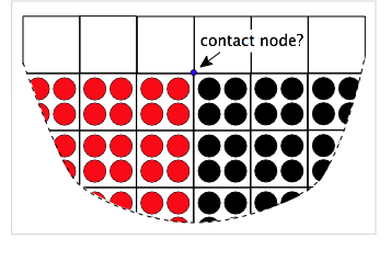
An alternate use of volume screening is to screen out nodes that can potentially cause artifacts in the calculations. These problem nodes are invariably contact nodes that appear near the edge of the modeled object. The figure on the left shows two materials in contact near an edge. The blue node will be a multimaterial node. To detect contact and implement contact physics, the contact algorithm needs to calculate the normal to the contactin surface. But for edge nodes these calculations are difficult because the free surface will affect the normal calculation. As a result, the calculation may be inaccurate and the entire simulation can suffer.
This issue can often be fixed by ignoring problem edge nodes. In other words, it can be better to ignore contact on edge nodes then to include them with inaccurate surface normals. Because edge nodes are near empty cells, their total volume from particles will always be less than 1.0. The node in the figure will have total relative volume close to 0.5. Thus to screen out edge nodes, you can set (Vmin) parameter to a value below 1.0, often around 0.5. The goal is to screen out edge nodes but to not screen out any nodes within the object. The actual value is problem dependent. When edge nodes appear to be causing problems in contact calculations, start increasing (Vmin) parameter between 0.0 and 1.0 until the simulations improve and hopefully before getting too close to 1.0.
Explicit Crack Contact Detection
ContactPosition Command
When using the displacement check to detect contact, the code extrapolates particle positions within each velocity. The opening displacement normal the the surfaces is found from
[math]\displaystyle{ \delta_n = (\vec x_b-\vec x_a)\cdot\hat n }[/math]
where xa and xb are the extrapolated positions for material above and below the surface and n is the surface normal. But, inherent imprecision of surfaces in MPM (or any particle method) causes a problem. Consider the two surfaces in the figure n the right. When calculations start, their nodal positions extrapolated to common nodes will show a positive separation. Calculations with MPM shape functions show that the calculated separation based on positions of two materials precisely in contact is
[math]\displaystyle{ \delta_n \approx 0.8\Delta x }[/math]
where Δx is the cell dimension along the contacting axis. In other words, a contact criterion of δn<0 for contact would not work
References
- ↑ S. G. Bardenhagen, J. E. Guilkey, K. M. Roessig, J. U. Brackbill, W. M. Witzel, and J. C. Foster, "An Improved Contact Algorithm for the Material Point Method and Application to Stress Propagation in Granular Material," Computer Modeling in Engineering & Sciences, 2, 509-522 (2001).
- ↑ Jim Guilkey, personal communication, 2012

