Difference between revisions of "3D MPM Shape Commands"
| Line 98: | Line 98: | ||
<li><tt>style='tripts'</tt> or <tt>style='trivectors'</tt>: define a triclinic shape, which is an eight-corned box for which opposite faces are parallel, but the corners need not meet at right angles. For this style, you specify 4 points (or 12 coordinates). For <code>tripts</code>, the 4 points are the points labeled in the figure below. For <tt>trivectors</tt>, the first point is point 1 (the origin) and the remaining three points are the vectors between the shape's origin that point. | <li><tt>style='tripts'</tt> or <tt>style='trivectors'</tt>: define a triclinic shape, which is an eight-corned box for which opposite faces are parallel, but the corners need not meet at right angles. For this style, you specify 4 points (or 12 coordinates). For <code>tripts</code>, the 4 points are the points labeled in the figure below. For <tt>trivectors</tt>, the first point is point 1 (the origin) and the remaining three points are the vectors between the shape's origin that point. | ||
File:triclinic.jpg|center]] | [[File:triclinic.jpg|center]] | ||
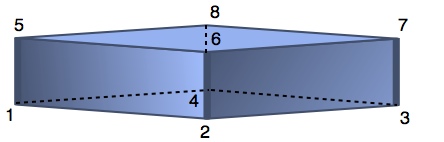
<li><tt>style='15482637'</tt>: define an arbitrarily shaped 8-corner box. The provided numbers map the order of the provided 8 points (or 24 coordinates) to the standard order shown in the figure below. | <li><tt>style='15482637'</tt>: define an arbitrarily shaped 8-corner box. The provided numbers map the order of the provided 8 points (or 24 coordinates) to the standard order shown in the figure below. | ||
Revision as of 10:22, 7 December 2013
These shape commands are used in 3D MPM simulations within Region and Hole commands to discretize an object for the calculations. Besides these shapes, you can also discretize objects directly from a stack of images.
Box Command
A scripted Box command defines a region to be filled with material points or to be defined as a hole:
Box (xmin),(xmax),(ymin),(ymax),(zmin),(zmax)
In XML files, the command is:
<Box xmin='(xmin)' xmax='(xmax)' ymin='(ymin)' ymax='(ymax)'
                   zmin='(zmin)' zmax='(zmax)'/>
where
- (xmin),(xmax),(ymin),(ymax),(zmin), and (zmax) are the x, y, and z extents of the cubical volume. If xmax<xmin, ymax<ymin, or zmax<zmin, they will be automatically switched to define the box. The units are mm (or determined by a units attribute in XML files).
If the defined cubical volume overlaps regions that already have material points or previously was defined as a hole, those regions will be ignored.
Sphere Command
A scripted Sphere command defines a region to be filled with material points or to be defined as a hole:
Sphere (xmin),(xmax),(ymin),(ymax),(zmin),(zmax)
In XML files, the command is:
<Sphere xmin='(xmin)' xmax='(xmax)' ymin='(ymin)' ymax='(ymax)'
                      zmin='(zmin)' zmax='(zmax)'/>
where
- (xmin),(xmax),(ymin),(ymax),(zmin), and (zmax) are the x, y, and z extents of the cubical volume that encloses the spherical volume. If xmax<xmin, ymax<ymin, or zmax<zmin, they will be automatically switched to define the box. The units are mm (or determined by a units attribute in XML files).
If the defined spherical volume overlaps regions that already have material points or previously was defined as a hole, those regions will be ignored.
Cylinder Command
A scripted Cylinder command defines a cylindrical or conical region to be filled with material points or to be defined as a hole:
Cylinder (xmin),(xmax),(ymin),(ymax),(zmin),(zmax),(axis),<(radius)>
In XML files, the command is:
<Cylinder xmin='(xmin)' xmax='(xmax)' ymin='(ymin)' ymax='(ymax)'
          zmin='(zmin)' zmax='(zmax)' axis='(axis)' radius='(radius)'/>
where
- (xmin),(xmax),(ymin),(ymax),(zmin), and (zmax) are the x, y, and z extents of the cubical volume that encloses the cylindrical or conical volume. If xmax<xmin, ymax<ymin, or zmax<zmin, they will be automatically switched to define the box. The units are mm (or determined by a units attribute in XML files).
- (axis) is 1, 2, or 3 for the axial direction of the cylinder to be in the x, y, or z direction, respectively. This command can only define cylinders aligned with one of the global axes.
- (radius) is an optional parameter with a value between -1 and 1. This value gives the relative radius of the cylinder at the top (if > 0) or at the bottom of the cylinder (if < 0) while the opposite end will have relative radius of 1. Entering 0 gives a cone with a point on the top (to get a cone with point on the bottom enter a small negative number). The radius of the cylinder varies linearly along its length.
If the defined cylindrical or conical volume overlaps regions that already have material points or previously were defined as a hole, those regions will be ignored.
Torus Command
A scripted Torus command defines a defines a toroidal volume to be filled with material points or defined as a hole:
Torus (xmin),(xmax),(ymin),(ymax),(zmin),(zmax),(axis),<(radius)>
In XML files, the command is:
<Torus xmin='(xmin)' xmax='(xmax)' ymin='(ymin)' ymax='(ymax)'
       zmin='(zmin)' zmax='(zmax)' axis='(axis)' radius='(radius)'/>
where
- (xmin),(xmax),(ymin),(ymax),(zmin), and (zmax) are the x, y, and z extents used to define the torus (see below). If xmax<xmin, ymax<ymin, or zmax<zmin, they will be automatically switched to define the box. The units are mm (or determined by a units attribute in XML files).
- (axis) is 1, 2, or 3 for the normal direction to the plane of the torus to be in the x, y, or z direction, respectively.
- (radius) is an optional parameter to define the radius of the toroidal ring cross section in the plane of the torus.
The (axis) parameter specifies the normal direction to the plane of the torus. The bounds for the directions in the plane of the torus (e.g., x and y bounds when (axis) is 3) define an ellipsoid (or circle if the bounds have the same range) that runs through the center of the torodial ring. The bounds in the direction of the axis define top and bottom for the cross-section of the torodial ring. The cross section will be a circle with radius given by half the distance between the top and bottom. To have an eliptical cross section, you can specify optional (radius) parameter to define the radius of the cross section in the plane of the torus (while top and bottom give radius of the cross section in the axis direction).
If the defined toroidal volume overlaps regions that already have material points or previously were defined as a hole, those regions will be ignored.
Polyhedron
The Polyhedron command (current only in XML files fills or empties an arbitrary 3D shape specified by describing the object as a collection of triangular faces. specified with one or more faces</a> commands subordinate to the Polyhedron command.
<Polyhedron>
   <faces style='(style)'>
1.496206e+002  2.879507e+000  1.775602e+002
5.361129e+001  3.039185e+000  1.498799e+002
1.496158e+002  2.209645e+000  1.775729e+002
    ...
   </faces>
 <Polyhedron>
Within the <Polyhedon> block, one or more <faces> blocks defines one or more polyhedra whose shape is determined by the style attribute. The numbers within each <faces> block are 3D coordinates. The number of coordinates entered depends on the style option being used. These options will grow as needed to solve new problems as they arise. Here are the currently available options:
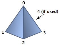
- style='pyramid': define a pyramid shape for which the first point is the apex of the pyramid and the remaining 3 or 4 points define the base. With 3 base points (4 total points), the shape is a tetrahedron; with 4 base points (5 total points), the shape is a pyramid with a quadrilaterial base. If the 4 base points are not coplanar, the base will have two face triangles connected by a line between the 1st and 3rd points.
- style='tripts' or style='trivectors': define a triclinic shape, which is an eight-corned box for which opposite faces are parallel, but the corners need not meet at right angles. For this style, you specify 4 points (or 12 coordinates). For
tripts, the 4 points are the points labeled in the figure below. For trivectors, the first point is point 1 (the origin) and the remaining three points are the vectors between the shape's origin that point.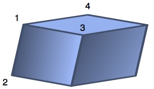
- style='15482637': define an arbitrarily shaped 8-corner box. The provided numbers map the order of the provided 8 points (or 24 coordinates) to the standard order shown in the figure below.


Within the <faces> block, all the data needed for the selected style are entered in a free format. The only requirements are the the correct number of valid numeric data points for the choosen style are provided and that the points are delimited by white space, commas, colons, and/or semicolons. The number of points per line does not matter and multiple delimiters between numbers can be used if desired.