Difference between revisions of "Isotropic Material Failure Surface"
| Line 8: | Line 8: | ||
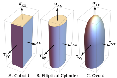
[[File:FailureSurfacePlots.png|400px|right]] | [[File:FailureSurfacePlots.png|400px|right]] | ||
Maximum principal failure stress failure surfaces are shown in the figure. Which surface to use for initiation is determined by the <tt>tractionFailureSurface</tt> property of the parent [[Isotropic Softening Material|isotropic softening material]]. The calculation for initial transpose these surface to principle stress space. The details are given in Ref. . | Maximum principal failure stress failure surfaces are shown in the figure. Which surface to use for initiation is determined by the <tt>tractionFailureSurface</tt> property of the parent [[Isotropic Softening Material|isotropic softening material]]. The calculation for initial transpose these surface to principle stress space. The details are given in Ref. <ref name="dmGen"/>. | ||
When viewed down the <math>\sigma_1=\sigma_2=\sigma_3</math> diagonal, the 3D surface is a hexagonal rod with point-to-point diagonal equal to <math>\tau_t</math> and apex at <math>\sigma_1=\sigma_2=\sigma_3=\sigma_n</math>. For tensile failure, the crack normal is along the maximum principal stress direction; for shear failure, it is rotated 45 degrees from the principal stress directions. | When viewed down the <math>\sigma_1=\sigma_2=\sigma_3</math> diagonal, the 3D surface is a hexagonal rod with point-to-point diagonal equal to <math>\tau_t</math> and apex at <math>\sigma_1=\sigma_2=\sigma_3=\sigma_n</math>. For tensile failure, the crack normal is along the maximum principal stress direction; for shear failure, it is rotated 45 degrees from the principal stress directions. | ||
Revision as of 13:27, 31 January 2023
Introduction
This damage initiation law predicts that failure initiates when maximum principal stress exceeds tensile strength of the material or when maximum shear stress exceeds shear strength of the material. It can also model pressure-dependent initiation stresses. Because it deals with principal stresses and tensile failure is the same regardless of direction, this law is only appropriate for isotropic materials such as an IsoSoftening material.
Failure Surface
Maximum principal failure stress failure surfaces are shown in the figure. Which surface to use for initiation is determined by the tractionFailureSurface property of the parent isotropic softening material. The calculation for initial transpose these surface to principle stress space. The details are given in Ref. [1].
When viewed down the [math]\displaystyle{ \sigma_1=\sigma_2=\sigma_3 }[/math] diagonal, the 3D surface is a hexagonal rod with point-to-point diagonal equal to [math]\displaystyle{ \tau_t }[/math] and apex at [math]\displaystyle{ \sigma_1=\sigma_2=\sigma_3=\sigma_n }[/math]. For tensile failure, the crack normal is along the maximum principal stress direction; for shear failure, it is rotated 45 degrees from the principal stress directions.
Note this failure criterion never fails under hydrostatic compression. Compression failure only occurs if the principal stress point moves far enough from the diagonal to reach the shear failure surface. The failure process is then by shear.
Damage Law Properties
The following table lists the input properties for maximum principal stress failure surface:
| Property | Description | Units | Default |
|---|---|---|---|
| sigmac | Critical tensile stress for failure | pressure units | infinite |
| tauc | Critical shear stress for failure | pressure units | infinite |
References
- ↑ J. A. Nairn, "Generalization of Anisotropic Damage Mechanics Modeling in the Material Point Method," Int. J. for Numerical Methods in Engineering, in press (2022).
