Difference between revisions of "Isotropic Material Failure Surface"
| Line 6: | Line 6: | ||
== Failure Surface == | == Failure Surface == | ||
[[File:MaxPrinciple.png|right]] | |||
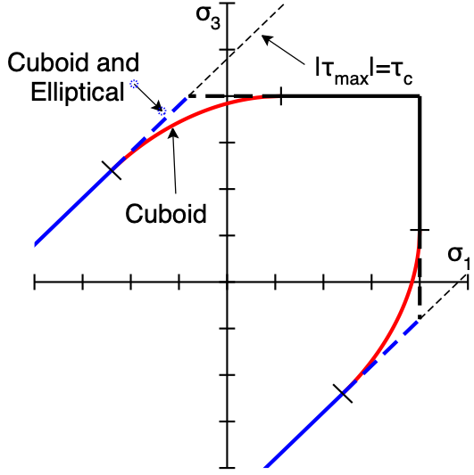
Maximum principle failure stress surfaces for 2D and 3D simulations are shown in the figure. When viewed down the $\sigma_1=\sigma_2=\sigma_3$ diagonal, the 3D surface is hexagonal rod with point-to-point diagonal equal to $\tau_t$ and apex at $\sigma_1=\sigma_2=\sigma_3=\sigma_n$. For tensile failure, the crack normal is along the maximum principle stress direction; for shear failure, it is rotated 45$^{\circ}$ from the principle stress directions. The use of two strengths are to connect the analysis of opening and shear failure or to tensile (mode I) and shear (modes II and III) fracture mechanics. The dashed line in Fig.~\ref{initiate}A is an example of an all alternate criterion, whose choice would require only trivial modifications. | |||
== Damage Law Properties == | == Damage Law Properties == | ||
Revision as of 14:24, 25 December 2016
Introduction
This damage initiation law predict that failure initiates when maximum principal stress exceeds tensile strength of the material or when maximum shear stress exceeds shear strength of the material. Because it deals with principal stresses and tensile failure is the same regardless of direction, this law is only appropriate for isotropic materials such as IsoSoftening material.
Failure Surface
Maximum principle failure stress surfaces for 2D and 3D simulations are shown in the figure. When viewed down the $\sigma_1=\sigma_2=\sigma_3$ diagonal, the 3D surface is hexagonal rod with point-to-point diagonal equal to $\tau_t$ and apex at $\sigma_1=\sigma_2=\sigma_3=\sigma_n$. For tensile failure, the crack normal is along the maximum principle stress direction; for shear failure, it is rotated 45$^{\circ}$ from the principle stress directions. The use of two strengths are to connect the analysis of opening and shear failure or to tensile (mode I) and shear (modes II and III) fracture mechanics. The dashed line in Fig.~\ref{initiate}A is an example of an all alternate criterion, whose choice would require only trivial modifications.
Damage Law Properties
This table lists the available damage initiation law. Click each one for more details and information on their properties.
| Name | ID | Description |
|---|---|---|
| MaxPrinciple | 1 | Damage initiates with principle stress exceeds tensile strength or when maximum shear stress exceeds the shear strength. |
It is relatively easy to write code for new damage initiation laws, if needed.
